
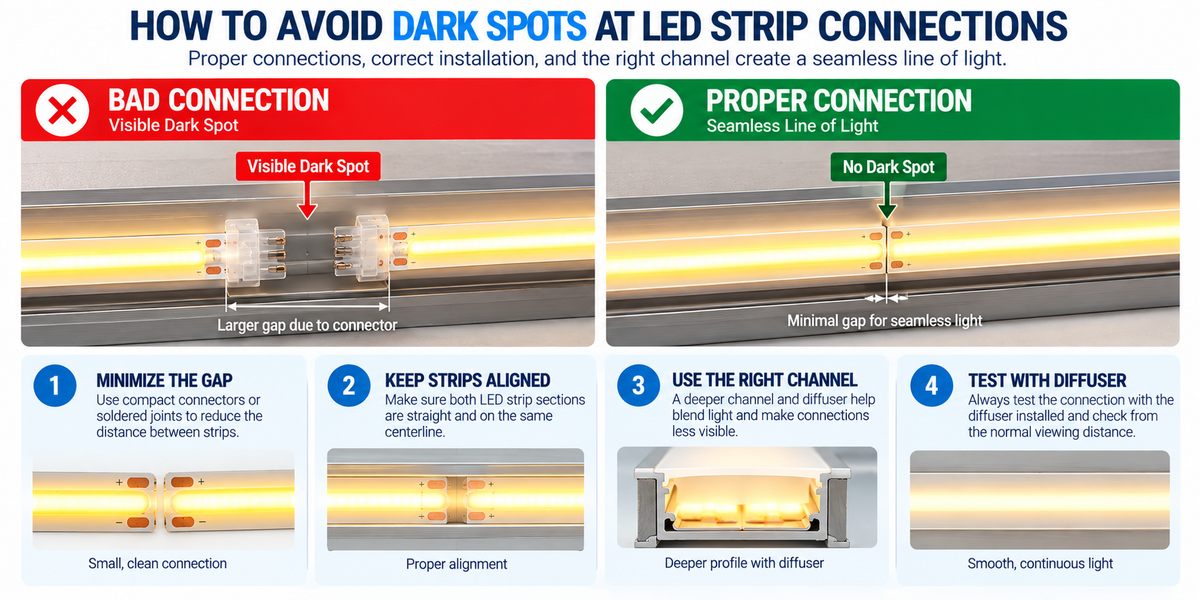
A well-designed LED strip installation should create a smooth, continuous line of light.
But one problem often becomes visible after installation:
Dark spots at LED strip connections.
You may have a beautiful continuous run of COB lighting, but where two sections meet, a darker area suddenly appears.
This can be especially noticeable in:
- Cove lighting
- Under-cabinet lighting
- Retail displays
- Shelving
- Aluminum channels
- Architectural linear lighting
- Hotels and restaurants
- High-end residential installations
The good news is that many connection dark spots can be prevented during the design and installation stage.
The key is understanding why the dark area appears in the first place.
What Is a Dark Spot at an LED Strip Connection?
A dark spot is a visible reduction in light at the point where two LED strip sections meet.
Instead of seeing:
──────────── Continuous Light ────────────
you may see:
─────────── Light ── DARK ── Light ───────────
The electrical connection may work perfectly.
Both LED strip sections may illuminate normally.
But the physical distance between the illuminated portions creates a visible interruption.
This means a dark spot is not always an electrical problem.
Very often, it is an optical and mechanical installation problem.
Why Do Dark Spots Happen?
The most common cause is simple:
The illuminated sections of the two LED strips are too far apart.
This can happen because of:
- Large solderless connectors
- Long cut sections
- Poor strip alignment
- Excessive wire between sections
- Large solder joints
- Incorrect cutting
- Channel geometry
- Diffuser distance
- Strip movement after installation
Even a relatively small physical gap can become visible through a diffuser.
COB LED Strips Help Create Smoother Light
COB LED strips are particularly useful when the goal is a continuous line of light.
COB technology uses a dense arrangement of LEDs beneath a continuous phosphor layer.
This produces a much smoother appearance than traditional widely spaced LED packages.
For applications such as:
- Aluminum channels
- Shelves
- Cabinets
- Cove lighting
- Architectural details
COB can significantly reduce visible dotting.
However, using COB does not automatically eliminate dark spots at connections.
If the physical gap between two COB sections is too large, the interruption may still be visible.
The Connection Is Often the Weakest Optical Point
Consider a long COB installation.
The strip itself may produce:
Smooth Light → Smooth Light → Smooth Light
Then two strips are joined with a connector.
Suddenly:
Smooth Light → Connector Gap → Smooth Light
The connector itself does not emit light.
Therefore, its physical length can create an unlit section.
The wider the connection area, the more likely the gap is to become visible.
Solderless Connectors Can Create Larger Gaps
Solderless connectors are convenient because they can simplify installation.
But some connector designs require additional physical space between the illuminated portions of the LED strips.
A typical connection may look like:
COB Strip → Connector → COB Strip
The connector body may occupy several millimeters of space.
If the strip is close to the diffuser, that gap can become visible.
This is particularly important in:
- Shallow aluminum channels
- Visible linear fixtures
- High-end architectural installations
Connector Size Matters
Not all LED strip connectors have the same dimensions.
Before using a connector inside an aluminum channel, check:
- Connector width
- Connector length
- Connector height
- Channel internal width
- Channel depth
- Diffuser clearance
A connector may electrically fit the strip but still create an undesirable optical result. Dimensions for each part are listed in our wire and connectors collection, and each profile page in the channel collection includes a dimensioned drawing.
Soldering Can Reduce the Connection Gap
For installations where seamless appearance is especially important, a carefully made soldered connection may allow the two LED strip sections to sit closer together than some bulky solderless connectors.
A compact soldered joint can potentially reduce the unlit distance between:
Last illuminated section of Strip A
and:
First illuminated section of Strip B
However, soldering must be performed correctly.
Poor soldering can create its own problems.
Poor Solder Joints Can Cause Electrical Dark Spots
Not every dark connection is caused by physical spacing.
A poor electrical connection can also cause:
- Reduced voltage
- Intermittent operation
- Flickering
- One color not working
- Reduced brightness near the connection
Possible causes include:
- Cold solder joints
- Insufficient solder
- Damaged copper pads
- Loose wires
- Incorrect polarity
- Poor connector contact
If the LEDs near the connection are actually dimmer—not simply separated by a dark gap—check the electrical connection.
Optical Gap vs. Electrical Problem
This is an important troubleshooting distinction.
Optical Gap
Both strip sections have normal brightness.
But there is a dark physical space between them.
Likely causes:
- Connector size
- Strip spacing
- Diffuser geometry
Electrical Problem
One section becomes dim, unstable, or does not illuminate correctly.
Possible causes:
- Poor connection
- Voltage drop
- Damaged pad
- Wiring problem
- Controller issue
Diagnosing the correct problem prevents unnecessary component replacement.
Cut the LED Strip Only at Approved Cut Points
LED strips should be cut only at the designated cutting locations specified by the manufacturer.
Cutting in the wrong place can:
- Damage the electrical circuit
- Remove usable copper pad area
- Damage LEDs
- Make connection difficult
- Create unnecessary spacing
Always locate the strip's marked cut point before cutting. The cut interval for each of our COB strips is listed on its product page.
Make Clean, Straight Cuts
Even when cutting at the correct location, the quality of the cut matters.
An angled or rough cut can reduce usable pad area and make it difficult to position two strips close together.
For a clean connection:
- Identify the approved cut line.
- Use an appropriate cutting tool.
- Make a straight cut.
- Avoid damaging adjacent LEDs or components.
- Inspect the copper pads before connecting.
A precise cut makes the next connection easier and cleaner.
Keep the Two Strip Sections Close
When creating a continuous visual line, minimize unnecessary distance between the two illuminated strip sections.
Instead of:
Strip → Large Gap → Strip
aim for:
Strip → Compact Connection → Strip
while still maintaining a safe and reliable electrical connection.
Do not force the strips together in a way that damages:
- Copper pads
- Solder joints
- PCB
- LEDs
The goal is a compact and mechanically reliable connection.
Strip Alignment Matters
Two LED strips should generally be aligned along the same centerline when installed inside a straight channel.
If one strip shifts sideways at the joint, the diffuser may reveal:
- Uneven brightness
- Shadowing
- Visible transition
- Uneven line width
Before securing the strips permanently, inspect the connection from above.
The two sections should form a clean continuous path.
Do Not Allow the Strip to Lift at the Connection
Connections sometimes create mechanical tension.
The strip may lift away from the bottom of the aluminum channel around the joint.
This can change the distance between the LED strip and diffuser.
The result may appear as:
- Brighter area
- Darker area
- Uneven diffusion
Make sure the strip remains properly seated against the channel around the connection. Good contact also matters for heat spreading.
Aluminum Channel Depth Can Hide Small Gaps
The distance between the LED strip and diffuser affects how well the light blends.
A deeper channel provides more mixing distance — compare the shallow BN252 with the deeper BN256.
Conceptually:
LED Strip
↓
Light Mixing Space
↓
Diffuser
With more appropriate mixing distance, a small gap may become less noticeable.
In a very shallow channel, the diffuser sits close to the LED source, making variations easier to see.
Shallow Channels Require More Care
Low-profile channels are useful when installation space is limited.
But because the LED strip is close to the diffuser, they can reveal:
- Connection gaps
- Uneven strip placement
- Bright spots
- Changes in LED density
For shallow profiles, connection quality becomes especially important.
The Diffuser Makes a Difference
Diffusers help blend light from the LED strip.
Common options may include:
A more diffusing cover can sometimes help reduce the visibility of small variations in the light source.
However, there is a tradeoff.
More diffusion may also reduce light transmission.
The correct diffuser depends on the desired balance between:
Brightness + Uniformity
A Diffuser Cannot Fix a Large Gap
This is important.
A diffuser can help blend a small connection gap.
But if the distance between illuminated sections is too large, the dark area may remain visible regardless of diffuser type.
The best approach is:
Minimize the Gap First → Use Appropriate Diffusion Second
Do not rely on the diffuser to correct poor strip placement.
COB Density Matters
Not all COB LED strips are identical.
Differences can include:
- LED density — for example 384 LEDs/m versus 480 LEDs/m
- Wattage
- PCB width
- Cut interval
- Phosphor design
- Brightness
A higher-density continuous-light design can improve overall uniformity.
But the connection still creates a physical transition that must be managed correctly.
Cut Interval Is Important
The strip's cut interval determines where sections can be shortened.
A shorter cut interval can provide more installation flexibility.
Suppose an architectural channel requires exactly:
63 inches
but the strip can only be cut at relatively long intervals.
You may end up with:
- Excess space at the end
- Difficult connection placement
- Uneven gaps
Therefore, cut interval can be an important specification for custom architectural projects. Check it on the product page before specifying a strip for a fixed-length channel.
Plan Connections Before Installing the Channel
Do not wait until the strip is already inside the channel to decide where all connections will occur.
Before installation, identify:
- Channel joints
- Strip cut points
- Feed locations
- Corners
- Controller locations
- Driver locations
- Connection points
Whenever practical, avoid placing a strip connection at the most visually critical point.
Avoid Aligning Every Joint in the Same Place
In large installations, the aluminum channel may also be assembled from multiple sections. Our profiles come in 8ft lengths, so long runs need fewer joints.
If possible, avoid creating:
Channel Joint + LED Strip Joint
at exactly the same location.
Why?
Because both transitions can increase the chance of a visible imperfection.
Staggering the joints may produce a cleaner finished installation.
Channel Joints Need Accurate Alignment
Two aluminum channels that are not aligned can cause the LED strip to:
- Bend
- Lift
- Shift sideways
- Change distance from the diffuser
This can create an apparent dark spot even when the strip connection itself is good.
For long architectural runs, carefully align adjoining channel sections. Recessed profiles in particular depend on an accurately prepared opening to stay aligned.
Corners Need Special Planning
Corners are another common location for dark areas.
Trying to sharply fold an LED strip around a 90-degree corner can:
- Damage the PCB
- Stress the copper conductors
- Lift the strip
- Create uneven lighting
Depending on the project, better solutions may include:
- Corner connectors
- Short wire connections
- Properly soldered corner joints
- Corner aluminum channels
- Flexible profiles
The correct method depends on the strip and installation. Our guide on corner LED channels covers the options in more detail.
Do Not Bend LED Strips Beyond Their Limits
Flexible does not mean infinitely bendable.
LED strips are generally designed to bend primarily in a specific direction.
Twisting or sharply folding the PCB can damage:
- Copper traces
- Components
- LEDs
- Solder joints
Follow the strip manufacturer's minimum bend requirements. For curved runs, a bendable channel is a better solution than forcing the strip.
RGB and RGBW Connections Require Extra Precision
Multi-channel strips have more electrical conductors.
For example:
RGB
may require multiple channel connections.
requires even more.
If one conductor has poor contact, one color may become:
- Dim
- Missing
- Intermittent
This can look like a dark or discolored connection.
Check every channel carefully, and confirm the controller wiring matches the strip's channel order.
CCT Strips Can Show Color Changes at Bad Connections
Tunable-white CCT strips typically use separate warm-white and cool-white channels.
If one connection is poor, the section after the joint may display:
- Different color temperature
- Reduced brightness
- Uneven white balance
This is not necessarily an optical gap.
It may be an electrical connection problem affecting one channel.
Waterproof LED Strips Require Additional Preparation
IP65 or other protected LED strips may have a coating or sleeve over the connection area.
Before making certain types of connections, the installer may need to prepare the connection area according to the manufacturer's instructions.
Improper preparation can result in:
- Poor electrical contact
- Connector misalignment
- Larger physical gaps
After the connection, the required environmental protection must also be restored appropriately. A waterproof surface-mount channel can provide additional protection for the completed run.
Do Not Sacrifice Waterproofing for Appearance
For outdoor or damp-location installations, minimizing a dark spot should never come at the expense of environmental protection.
The complete system must maintain the required protection for:
A visually perfect joint that allows moisture into the electrical connection is not a successful installation.
Voltage Drop Can Look Like a Dark Connection
Suppose the LEDs immediately after a connection are noticeably dimmer.
The connector may not necessarily be the problem.
The system may have excessive voltage drop.
Possible causes include:
- Long LED strip run
- Long feeder cable
- Undersized wire
- High current
- Poor connection resistance
Measure and evaluate the electrical system rather than assuming the visual transition is purely optical.
Power Injection Can Improve Long Runs
Long LED strip runs may require additional power feeds.
Instead of relying on power to travel through a very long section:
Driver → Long Strip → Long Strip → Long Strip
the system can use additional feed points where appropriate, usually run with jumper wire and connectors.
This can help maintain more consistent voltage and brightness.
However, power injection will not fix a physical dark gap caused by an oversized connector.
These are separate problems.
Example: Under-Cabinet Lighting
Imagine two COB strip sections meeting beneath a kitchen cabinet.
Poor Installation
COB → Large Connector → COB
The channel is shallow.
The diffuser sits close to the strip.
Result:
Visible dark section
Improved Installation
COB → Compact Connection → COB
The strips are carefully aligned inside an appropriate profile.
Result:
Much smoother visual transition
This small installation detail can significantly affect the finished appearance.
Example: Retail Shelf Lighting
Retail shelving often places the LED strip close to eye level.
That makes imperfections easier to notice.
A connection gap that might be invisible in a high ceiling cove could be obvious inside a display shelf.
For retail applications:
- Use COB where appropriate
- Minimize connection gaps
- Keep strips aligned
- Choose the channel carefully
- Test with the diffuser installed
Example: Commercial Cove Lighting
Cove lighting is usually viewed from farther away.
This can make small connection transitions less noticeable.
However, long uninterrupted lines of light make inconsistent brightness easier to detect.
For long commercial coves, consider:
- Connection placement
- Maximum run length
- Power injection
- Voltage drop
- Channel alignment
- Driver sizing
Optical and electrical uniformity both matter.
Test the Connection Before Final Installation
Before permanently closing the channel:
- Connect the strips.
- Power the system.
- Install the diffuser temporarily.
- View the lighting from the normal viewing position.
- Check the joint.
- Check brightness before and after the connection.
- Verify all colors if using RGB, RGBW, or CCT.
A connection that looks acceptable without the diffuser may look different once the cover is installed.
Test From the Actual Viewing Distance
Do not evaluate the installation only from a few inches away.
Ask:
Where will the customer actually see this light?
For example:
- Under cabinet: 3–6 ft away
- Retail shelf: 2–5 ft away
- Cove: much farther away
- Ceiling detail: viewed from below
Evaluate the lighting from realistic viewing positions.
Make a Mock-Up for Large Projects
For commercial installations involving hundreds of feet of LED strip, create a small test section first.
Include the actual:
- COB strip
- Connector or solder joint
- Aluminum channel
- Diffuser
- Driver
- Controller if applicable
Then evaluate:
- Dark spots
- Brightness
- Diffusion
- Color
- Connection quality
A small mock-up can prevent repeating the same visual problem throughout an entire project.
Connection Method Comparison
| Connection Method | Installation | Potential Gap | Best Consideration |
|---|---|---|---|
| Solderless Connector | Fast and convenient | Can be larger | Check dimensions carefully |
| Soldered Joint | Requires more skill | Can be compact | Good workmanship essential |
| Short Wire Jumper | Flexible positioning | Depends on spacing | Useful around obstacles/corners |
| Direct Continuous Strip | No joint | Minimal interruption | Limited by available length and run limits |
No method is best for every project.
Choose based on the installation requirements.
Common Causes of Dark Spots
Before troubleshooting, check for:
- Oversized connector
- Excessive strip spacing
- Poor solder joint
- Loose connector
- Misaligned strips
- Strip lifting from channel
- Incorrect cut
- Damaged copper pads
- Shallow channel
- Inadequate diffusion
- Voltage drop
- Poor channel alignment
- Corner installation problems
Identifying the actual cause is the first step toward correcting it.
How to Avoid Dark Spots: Step by Step
Step 1 — Choose the Right LED Strip
For seamless linear applications, consider an appropriate COB strip.
Step 2 — Choose the Channel
Confirm:
- Internal width
- Depth
- Diffuser type
- Strip compatibility
Step 3 — Plan Joint Locations
Avoid visually critical areas when possible.
Step 4 — Cut Correctly
Use only designated cut points.
Step 5 — Minimize Physical Gaps
Use an appropriate connection method.
Step 6 — Align the Strips
Keep both sections straight and centered.
Step 7 — Maintain Good Electrical Contact
Inspect connectors or solder joints carefully.
Step 8 — Check Voltage Drop
Especially for long installations.
Step 9 — Install the Diffuser
Evaluate the actual finished appearance.
Step 10 — Test Before Finalizing
Correct problems while the installation is still accessible.
Professional Installation Checklist
Before completing the project, confirm:
LED Strip
- Correct COB strip selected
- Correct width
- Correct voltage
- Correct cut points used
Connection
- Minimal practical gap
- Reliable electrical contact
- Correct polarity
- No damaged pads
- No mechanical stress
Channel
- Correct internal width
- Sections aligned
- Strip seated flat
- Suitable depth
- Diffuser properly installed
Electrical
- Driver correctly sized
- Controller correctly sized
- Wire gauge appropriate
- Voltage drop considered
- Power injection added where required
Visual
- No obvious dark connection gaps
- Uniform brightness
- Consistent color
- Joint tested through diffuser
- Appearance checked from normal viewing distance
The Best Connection Is Planned Before Installation
Many dark spots are difficult to fix after:
- Channels are recessed
- Cabinets are installed
- Drywall is finished
- Diffusers are cut
- Wiring is hidden
Planning connection locations before construction can save considerable time later.
For professional installations, treat LED strip joints as part of the lighting design—not as an afterthought.
Conclusion
Dark spots at LED strip connections are usually caused by either:
Physical Light Gaps
or
Electrical Connection Problems
For smooth architectural lighting, the goal is to minimize the distance between illuminated sections while maintaining a reliable electrical connection.
A professional installation combines:
COB LED Strip + Precise Cutting + Compact Connections + Proper Alignment + Appropriate Aluminum Channel + Diffuser + Correct Electrical Design
Solderless connectors can be convenient, but their physical dimensions should be considered carefully in visible linear lighting.
Soldered connections can sometimes create more compact transitions, but they require proper workmanship.
And even the best connection cannot compensate for excessive voltage drop or poor system design.
Plan the connection points early, test them through the actual diffuser, and evaluate the finished line of light before completing the installation.
That is the best way to achieve the smooth, continuous appearance expected from a professional LED strip project. If you would like help matching a strip, connector, and channel for a seamless run, contact our team for samples and wholesale pricing.
Frequently Asked Questions
Why is there a dark spot where two LED strips connect?
The most common cause is a physical gap between the illuminated portions of the two strips. Large connectors, poor alignment, or incorrect installation can make the gap more visible.
Do COB LED strips eliminate dark spots at connections?
COB strips provide smoother continuous light along the strip, but a large physical gap at a connection can still create a visible dark spot.
Are soldered connections better than solderless connectors for seamless lighting?
A compact soldered joint can sometimes reduce the physical gap compared with a bulky connector. However, soldering must be performed correctly and reliably.
Can an aluminum channel hide LED strip connection gaps?
An appropriate channel and diffuser can help blend small variations, especially when there is sufficient mixing distance. They cannot completely hide a large unlit gap.
Why is the LED strip dim after the connection?
If the strip itself becomes dimmer after the joint, check the electrical connection, voltage drop, wire size, and total run length rather than assuming it is simply an optical gap.
Does a deeper LED channel reduce dark spots?
A deeper profile can provide more distance between the strip and diffuser, which may improve light mixing. Actual results depend on the strip, profile, diffuser, and gap size.
Can solderless connectors fit inside every LED channel?
No. Always check the connector's width, height, and length against the channel's internal dimensions.
Should I test LED strip connections before installing the diffuser permanently?
Yes. Test the complete assembly with the diffuser installed and view it from the normal viewing distance before finalizing the installation.