
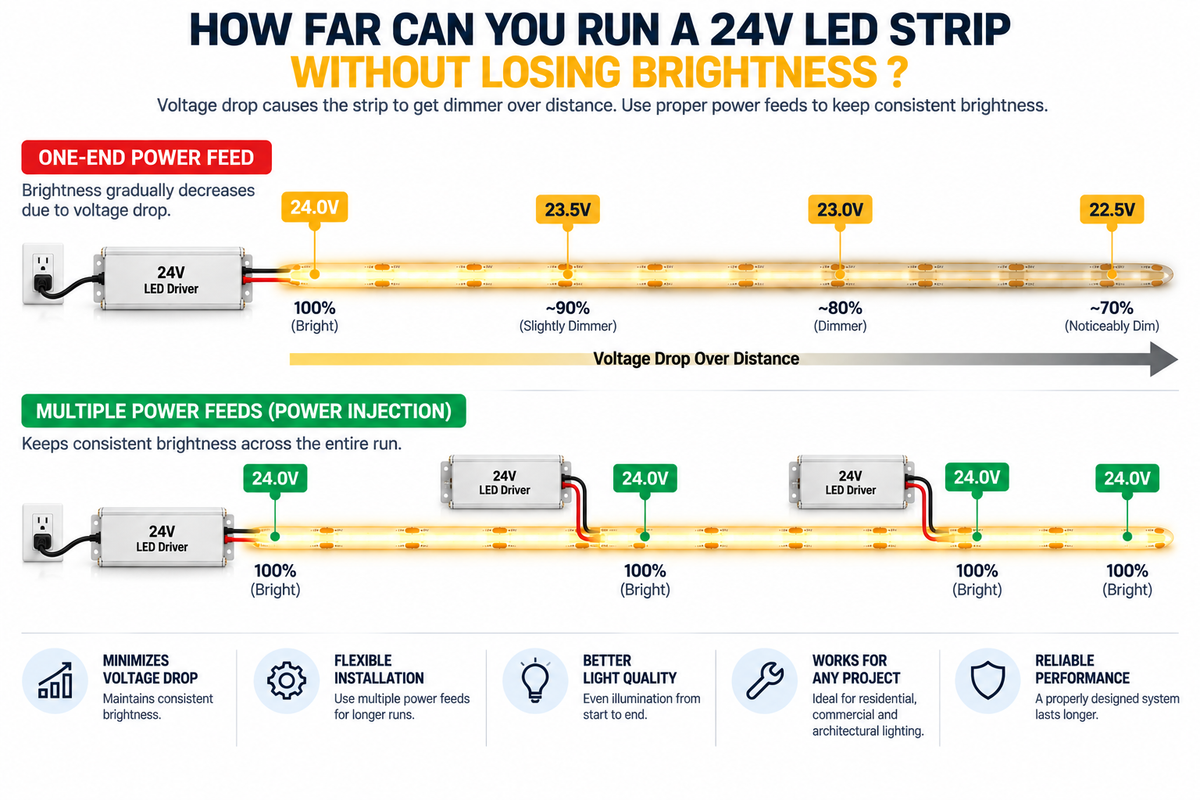
One of the most common questions when planning a large LED strip installation is:
How far can a 24V LED strip run before it starts losing brightness?
There is no single maximum distance that applies to every 24V LED strip.
Depending on the product and installation, one strip may maintain relatively consistent brightness over a longer distance while another may require an additional power feed much sooner.
The practical run length depends on factors including:
- LED strip wattage
- PCB design
- Copper thickness
- Current
- Feed-wire length
- Wire size
- Connection quality
- Power-feed configuration
- Manufacturer specifications
Understanding these factors is essential for contractors, electricians, lighting designers, and installers working with long COB LED strip runs.
Why Does an LED Strip Lose Brightness Over Distance?
LED strips conduct electricity through copper traces running along the flexible PCB.
Those traces have electrical resistance.
As current travels farther through the strip, some voltage is lost.
This is known as:
Voltage Drop
The farther electricity must travel—and the more current the system carries—the more noticeable the effect can become.
Eventually, the voltage available at the far end may be lower than at the beginning.
The result can be:
- Lower brightness
- Uneven illumination
- Color variation
- Poor performance at the end of the strip
What Does Voltage Drop Look Like on an LED Strip?
Imagine a long COB LED strip powered from only one end.
Near the power connection:
Bright → Bright → Bright
Farther away:
Bright → Slightly Dimmer → Dimmer
The change may be gradual rather than sudden.
This can make voltage drop difficult to notice until the complete installation is operating.
Why 24V Is Better Than 12V for Longer Runs
One reason 24V LED systems are commonly used for larger installations is that they require less current than 12V systems for the same wattage. Every strip in our COB LED strip range is 24V for this reason.
The basic formula is:
Current (A) = Power (W) ÷ Voltage (V)
Suppose an LED load requires:
120W
At 12V:
120W ÷ 12V = 10A
At 24V:
120W ÷ 24V = 5A
The 24V system carries half the current for the same power.
Lower current can help reduce voltage-drop problems in wiring and power distribution.
This does not mean that 24V strips can run indefinitely.
Voltage drop still occurs.
So How Many Feet Can a 24V LED Strip Run?
The correct answer is:
Use the maximum continuous run length specified for the particular LED strip.
There is no universal number for all 24V products.
Two 24V COB strips can have very different maximum recommended run lengths because they may have different:
- Wattage per foot
- PCB construction
- Copper thickness
- LED density
- Circuit architecture
For example, our 8mm 384 LEDs/m COB strip and 10mm 480 LEDs/m COB strip are both 24V but differ in PCB width and output, so each lists its own maximum run.
Therefore:
24V tells you the operating voltage—not the guaranteed maximum run length.
Why Wattage per Foot Matters
Higher-wattage strips require more electrical power.
For example:
Strip A
3 W/ft × 20 ft = 60W
Current at 24V:
60 ÷ 24 = 2.5A
Strip B
6 W/ft × 20 ft = 120W
Current at 24V:
120 ÷ 24 = 5A
Both strips are:
- 24V
- 20 ft long
But Strip B carries significantly more current.
That higher current can increase voltage-drop concerns.
This is why run length cannot be determined from voltage alone. Wattage per foot is listed on every COB strip product page.
Driver Wattage Does NOT Determine Maximum Strip Run Length
This is one of the most important points.
Suppose you have:
and a strip consuming:
5 W/ft
Mathematically:
300W ÷ 5 W/ft = 60 ft
That does not mean you should connect 60 continuous feet of strip from one end.
The driver may have enough total wattage, but the LED strip's PCB may not be designed to carry that current over the entire 60 ft.
These are two separate limits:
Driver Capacity
versus
Maximum Continuous Strip Run
Both must be respected.
What Happens When a Strip Run Is Too Long?
Several problems may appear.
1. Brightness Drops at the End
This is the most obvious symptom.
The beginning of the strip looks brighter than the far end.
2. Uneven Illumination
A long architectural line may gradually change brightness from one end to the other.
This can be especially noticeable in:
- Cove lighting
- Long corridors
- Retail shelves
- Linear ceiling details
- Hospitality projects
3. Color Can Become Inconsistent
Voltage drop can affect how some LED systems appear.
In color-changing installations, electrical differences between sections can create visible inconsistencies. This is worth particular attention with RGBW and CCT strips, where several channels share the same PCB.
4. Excessive Current Can Stress the Strip
Trying to carry too much current through a long PCB can create unnecessary electrical and thermal stress.
Always respect the manufacturer's specifications.
The Feed Wire Can Also Cause Voltage Drop
Voltage drop does not occur only inside the LED strip.
It can also happen in the wire between:
For example:
Driver is located close to the strip:
Short wire run → Lower wiring loss
Driver is located far away:
Long wire run → Greater potential voltage drop
This means even a properly sized LED strip run can perform poorly if the feed wiring is undersized or excessively long. Where the driver can sit inside the millwork beside the strip, a compact dimmable transformer keeps the low-voltage run short.
Wire Size Matters
A larger conductor generally has lower resistance than a smaller conductor of the same material and length.
The appropriate wire size depends on:
- Current
- Distance
- System voltage
- Installation method
- Acceptable voltage drop
- Applicable electrical requirements
For long-distance power feeds, wire sizing should be calculated rather than guessed. Available gauges are listed in our wire and connectors collection.
Connections Matter Too
Every connection adds another potential point of resistance.
Poor connections can contribute to:
- Voltage loss
- Heat
- Flickering
- Intermittent operation
- Uneven brightness
Check:
- Terminal blocks
- Solder joints
- Solderless connectors
- Wire splices
- Controller terminals
- Driver terminals
Connections should be secure and properly rated for the current.
What Is Power Injection?
Power injection means supplying power to additional points along the LED strip instead of relying on one feed point for the entire installation.
For example:
Instead of:
Driver → 40 ft Strip →
you might design:
Power Feed → Strip Section ← Additional Power Feed
or divide the installation into multiple electrically appropriate sections.
The exact configuration depends on the strip design and manufacturer instructions. Additional feeds are usually run with jumper wire and solderless connectors.
When Should You Consider Power Injection?
Power injection may be useful when:
- The installation exceeds the recommended single-feed run
- Brightness decreases toward the end
- The project contains long continuous architectural lines
- High-output strips are being used
- Voltage measurements show excessive drop
- The manufacturer recommends additional feed points
The goal is to prevent one strip section from carrying more current over distance than it was designed to handle.
Power Injection Does Not Mean Using a Higher Voltage
If you have a 24V LED strip, additional feed points should still provide the correct:
24V DC
Power injection means distributing the correct voltage more effectively.
It does not mean increasing the supply voltage to compensate for loss.
Do not intentionally over-voltage the strip.
Can You Power a Strip From Both Ends?
Some LED strip installations can benefit from feeding power at more than one location, including both ends, when the product and electrical design support it.
However, the exact wiring configuration should follow:
- Strip manufacturer instructions
- Driver requirements
- Controller architecture
- Electrical design
Do not assume that every LED strip should automatically be connected from both ends.
Breaking a Long Run Into Parallel Sections
For large projects, it is often better to divide one long installation into several shorter runs.
Instead of:
Driver → 60 ft Continuous Strip
the design may use:
Driver → Run A
Driver → Run B
Driver → Run C
Each run receives power separately.
This can improve:
- Voltage consistency
- Brightness uniformity
- Reliability
- Troubleshooting
- Maintenance
The runs can still appear visually continuous when installed properly.
Example: 60-Foot Cove Lighting Project
Suppose a project requires:
60 ft of 24V COB LED strip
Strip power:
4 W/ft
Total load:
60 × 4 = 240W
The first calculation tells us:
Total LED Load = 240W
But we still do not know whether the strip can operate as one 60-foot continuous run.
We must also check:
Maximum recommended run length
Suppose the selected strip should be installed in shorter runs.
The 60-foot project could then be divided into:
Run 1 – 20 ft
Run 2 – 20 ft
Run 3 – 20 ft
Each section receives an appropriate power feed — three 100W drivers would suit this layout, or one larger driver with properly sized distribution.
The architectural line can remain visually continuous while the electrical system is divided properly.
Example: Long Retail Shelving
Imagine a store with:
80 ft of illuminated shelving
Trying to power all 80 ft as one continuous strip from one end may create serious consistency problems.
A better design may divide the shelving into several zones.
For example:
Shelf Zone A → Driver/Feed → COB Strip
Shelf Zone B → Driver/Feed → COB Strip
Shelf Zone C → Driver/Feed → COB Strip
Shelf Zone D → Driver/Feed → COB Strip
The zones can still be controlled together using compatible controllers. Our guide on synchronizing multiple LED strip zones explains how to group them under one remote.
Multiple Drivers Can Help on Large Projects
For large distributed installations, using multiple smaller drivers can sometimes be more practical than one large centralized driver.
Benefits may include:
- Shorter low-voltage wiring runs
- Easier zoning
- Better voltage-drop management
- Easier troubleshooting
- Reduced impact if one driver fails
Driver architecture should be based on the physical layout of the project. Our range runs from 30W to 300W, including models with an integrated junction box for accessible installations.
Controller Location Can Affect the Design
If a controller is installed between the driver and strip:
Driver → Controller → LED Strip
the wiring between all three components matters.
Long cable distances can contribute to voltage drop.
For large installations, controllers may sometimes be positioned closer to their respective lighting zones. RF controllers and remotes make this practical because the receiver does not need to be within reach of the user.
This can reduce long high-current low-voltage cable runs.
Controller Capacity Must Also Be Checked
Suppose:
Driver = 300W
LED load = 220W
Controller capacity = 150W
The driver may be large enough, but the controller is not.
Long-run planning therefore requires checking:
- Strip maximum run
- Driver capacity
- Controller capacity
- Wire capacity
- Voltage drop
Every component matters.
COB LED Strips and Long Runs
COB strips provide a smooth, continuous-looking line of light, making them excellent for long architectural installations.
But COB technology does not eliminate voltage drop.
A COB strip still has:
- PCB resistance
- Current requirements
- Maximum run limitations
Therefore, long COB installations still require proper electrical planning.
Do Aluminum Channels Prevent Voltage Drop?
No.
Aluminum channels can help with:
- Mounting
- Protection
- Appearance
- Diffusion
- Heat spreading
But they do not solve electrical voltage drop.
Voltage drop must be addressed through proper:
- Strip selection
- Run length
- Wiring
- Power distribution
- Feed locations
How to Check for Voltage Drop
A multimeter can be used to compare voltage at different points.
For example:
Measure at the beginning of the strip.
Then measure near the end.
If:
Beginning = approximately 24V
but
End = noticeably lower
the system is experiencing voltage drop.
The acceptable amount depends on the product and performance requirements.
Visual Testing Is Also Important
Electrical measurements are important, but the final lighting appearance matters too.
Before completing a large installation:
- Install a representative test run.
- Operate it at full output.
- Compare the beginning and end.
- Check brightness consistency.
- Measure voltage if necessary.
- Test after the strip has been operating for a period of time.
This is especially useful for commercial and architectural projects.
Do Not Wait Until the Entire Project Is Installed
Voltage-drop problems are much easier to correct during planning.
Once:
- Channels are installed
- Ceilings are closed
- Cabinets are completed
- Wiring is hidden
- Finishes are installed
adding new power feeds can become expensive.
Plan the electrical architecture before installation.
How to Plan a Long 24V LED Strip Installation
Use this sequence:
Step 1 – Select the LED Strip
Confirm:
- 24V operation
- Wattage per foot
- Maximum recommended run
- Width
- IP rating
- Dimming/control type
Step 2 – Calculate Total Load
W/ft × Total Length = Total Watts
Step 3 – Divide the Project Into Appropriate Runs
Do not exceed the strip's recommended continuous-run requirements.
Step 4 – Select the Driver or Drivers
Make sure each driver has appropriate capacity.
Step 5 – Check Controller Capacity
Verify total and per-channel current where applicable.
Step 6 – Calculate Wiring Requirements
Consider current, distance, and voltage drop.
Step 7 – Plan Power Feeds
Determine whether multiple feeds or power injection are needed.
Step 8 – Test Before Final Installation
Confirm both electrical and visual performance.
Our guide on building a complete LED lighting system works through this selection process in more detail.
What Determines the Maximum Practical Run?
The practical run length is controlled by the weakest limitation in the system.
That may be:
LED Strip PCB
or
Driver
or
Controller
or
Wiring
or
Connector
or
Voltage Drop
A professional system must satisfy all of these conditions simultaneously.
24V vs. 12V for Large Projects
When compatible products are available, 24V systems can offer advantages for larger installations because the same power requires less current. Our dimmable drivers are switchable between 12V and 24V output, so the same driver can suit either design.
For example:
240W Load at 12V
240 ÷ 12 = 20A
240W Load at 24V
240 ÷ 24 = 10A
This can simplify some aspects of power distribution.
However, even at 24V, a 240W project may still need to be divided into multiple runs.
Common Long-Run Installation Mistakes
Avoid:
- Assuming every 24V strip has the same maximum run
- Calculating run length from driver wattage alone
- Connecting extremely long strips from one end
- Ignoring wattage per foot
- Ignoring wire size
- Ignoring feed-wire distance
- Using undersized connectors
- Exceeding controller capacity
- Trying to fix voltage drop by increasing supply voltage
- Assuming COB strips do not experience voltage drop
- Installing everything before testing
- Failing to plan additional power feeds
Long-Run Planning Checklist
Before installing a long 24V LED strip system, confirm:
LED Strip
- 24V compatible
- Wattage per foot known
- Maximum run length confirmed
- Correct strip width
- Appropriate IP rating
Power
- Total wattage calculated
- Driver capacity sufficient
- Correct 24V output
- Feed locations planned
Control
- Controller supports 24V
- Controller capacity sufficient
- Per-channel limits checked
Wiring
- Correct wire size
- Cable distances calculated
- Connections properly rated
- Voltage drop considered
Installation
- Additional feeds planned where needed
- Aluminum channels selected where appropriate
- Drivers/controllers accessible
- Full test completed before finishing construction
Conclusion
So, how far can you run a 24V LED strip without losing brightness?
There is no universal number.
The correct maximum run depends on the specific LED strip and the complete electrical design.
A 24V system can often provide advantages over 12V for longer installations because it operates at lower current for the same wattage.
But long 24V LED strips can still experience voltage drop.
For reliable results:
Check the manufacturer's maximum run length.
Calculate the wattage and current.
Size the driver correctly.
Check controller capacity.
Use appropriate wiring.
Plan additional power feeds when necessary.
Test the complete system before final installation.
For large commercial and architectural projects, dividing a long installation into several properly powered sections is often more reliable than trying to operate one extremely long continuous strip from a single feed point.
The goal is not simply to make the LED strip turn on.
The goal is to maintain consistent brightness from the beginning of the installation to the end.
If you would like a long run checked before you order, contact our team for run-length guidance and wholesale pricing.
Frequently Asked Questions
What is the maximum length of a 24V LED strip?
There is no universal maximum. It depends on the strip's wattage, PCB design, current, and manufacturer specifications. The figure for each of our COB strips is listed on its product page.
Does a 24V LED strip have less voltage drop than a 12V strip?
For the same power, a 24V system uses less current, which can help with voltage-drop management. However, 24V strips still experience voltage drop.
Can a larger LED driver let me run a longer continuous strip?
Not necessarily. Driver capacity and maximum continuous strip run are separate limitations.
How do I know if my LED strip has voltage drop?
Common signs include reduced brightness toward the end of the strip. Voltage measurements at the beginning and end can also help identify the problem.
What is power injection?
Power injection means supplying the correct voltage at additional points along an LED installation rather than relying on one power feed for the entire run, usually using jumper wire and connectors.
Can I increase the driver voltage to compensate for voltage drop?
Do not intentionally over-voltage a 24V strip. Instead, address the cause through proper wiring, run length, and power distribution.
Do COB LED strips experience voltage drop?
Yes. COB strips still carry current through a PCB and are subject to electrical resistance and maximum-run limitations.
Is one long strip better than several shorter runs?
For large installations, several properly powered shorter runs can often provide better brightness consistency and easier power distribution than one very long single-fed strip.